A 150 MHz Lowpass Filter
The Design
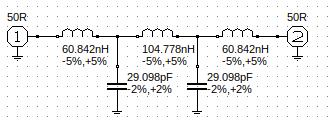
The design process is as simple as it gets. I used RFSim99 to come up with the following design for a 5th order Chebyshev with 0.1 dB passband ripple and a cutoff frequency of 150 MHz.

The Build
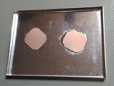
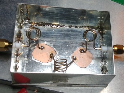
The idea I came up with was to use copper cladded FR4 material as capacitors and just solder patches of it to a enclosure made of tin. I cut the patches from 0.6 mm PCB base material and iteratively trimmed and measured them to the desired capacitance value.
For the inductors 3 resp. 4 windings with a diameter of around 8 mm should yield the desired inductance. Again the inductors were measured repeatedly while adjusting the turn spacing to yield the desired inductance value.


The picture above show one of the tin lids of the enclose with the soldered patches of FR4 base material. I used a SMD rework preheater to heat from below and some hot air from the top to reflow the patches on some solder that I had previously applied to the lid with the soldering iron.
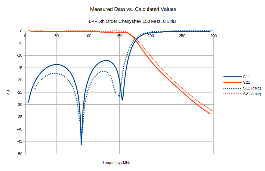
The following plot shows the measured performance without any further adjustements. The measuements match the calculation quite closely.
